
|
|
|
|
This project gave me a good taste of the rich intersection of Math and Computer Science. It was pretty interesting to implement the math, albeit frustrating sometimes. I think I liked the results of barycentric coordinates the most because it really cemented my understanding of the concept to actually hav to implement it.
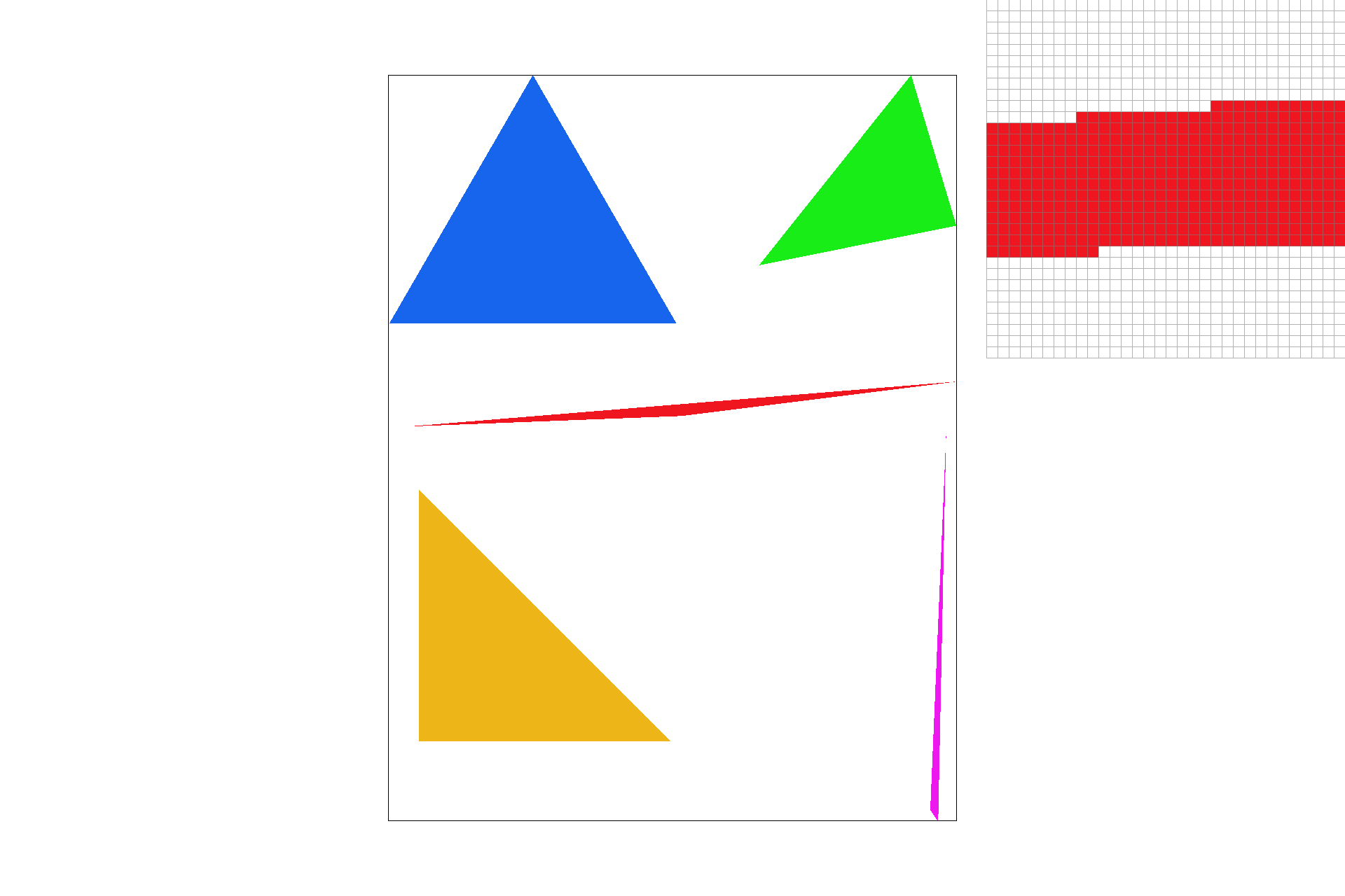
Triangles are characterized by 3 (x, y) points and 3 color channels, (R, G, B). We rasterized these triangles by using line tests. Imagine you drew three lines to connecting the three points. Now for each line, you check whether the point is on the "inside" of the line, with some slick linear algebra, (projecting onto the norm and checking the sign). If the sign is positive for all three, then the point is inside the triangle. I actually just check each sample within the bounding box of the triangle, so I am definitely no worse than that. Here's a picture of some sick jaggies! Part 2 here we come:)
I implemented supersampling by spliting each pixel into sqrt(sample_rate) subpixels and then averaging the color of each of those. This essentially blends the colors at the different subpoints smoothing out jaggies along the way!
I made two major changes to implement supersampling
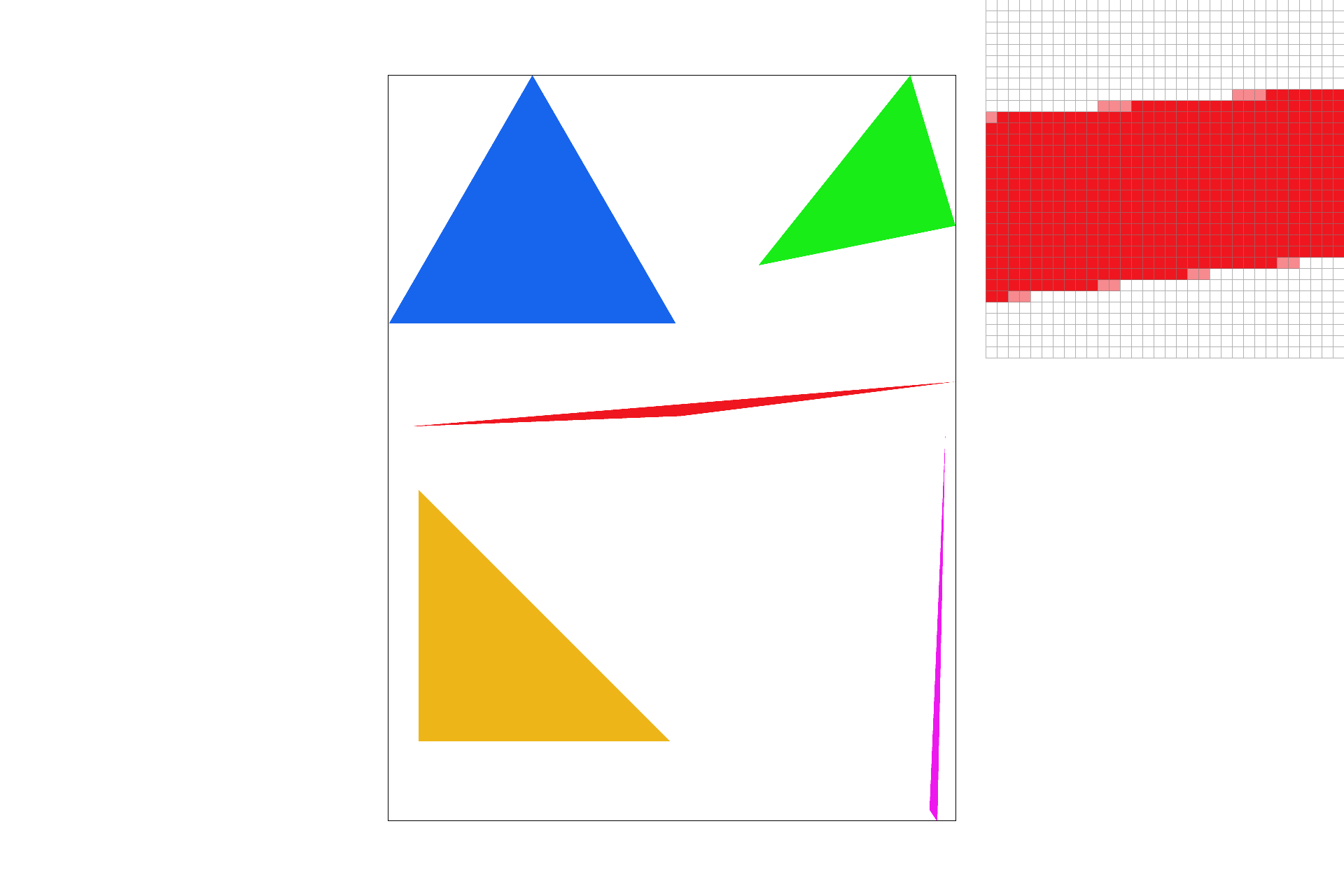
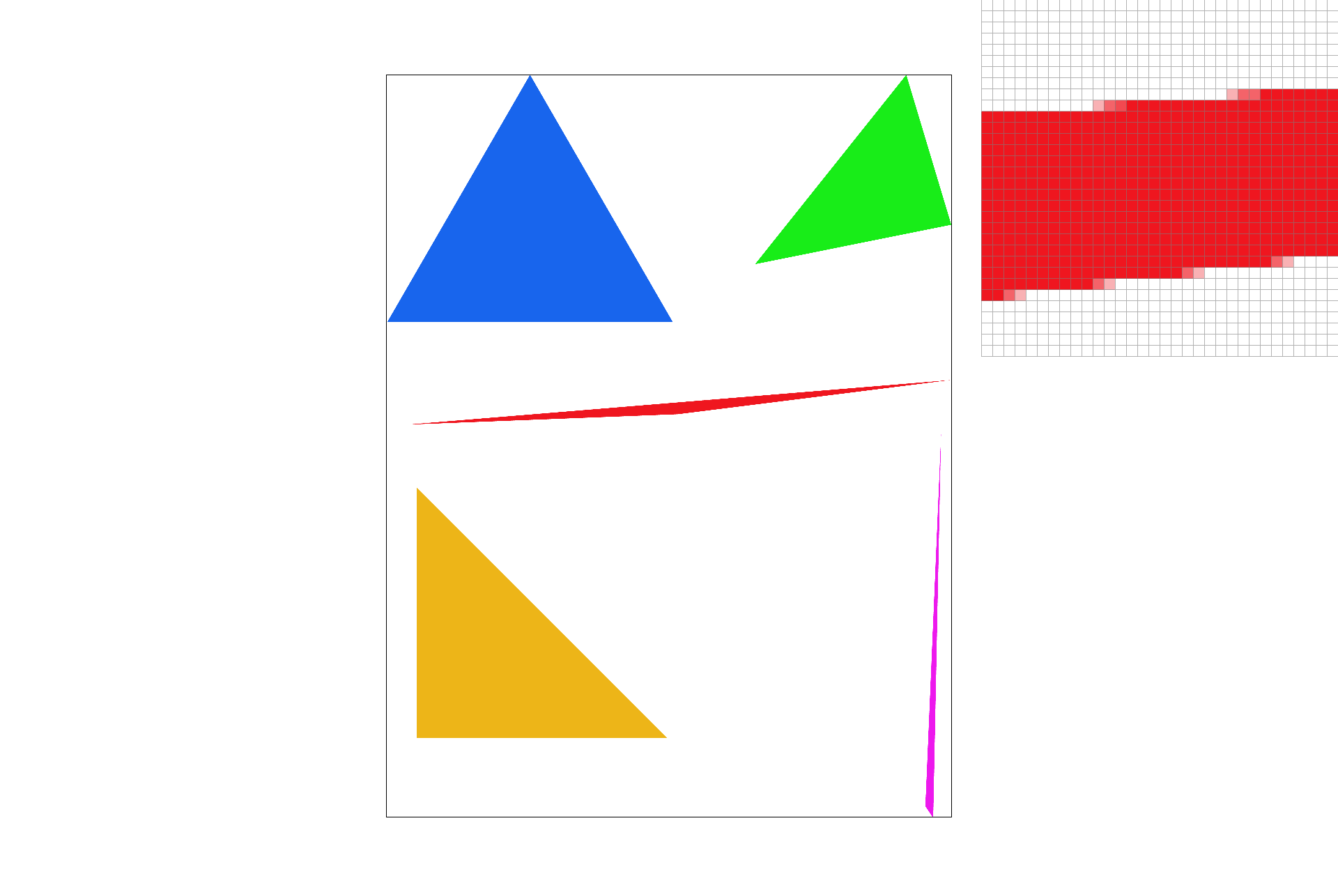
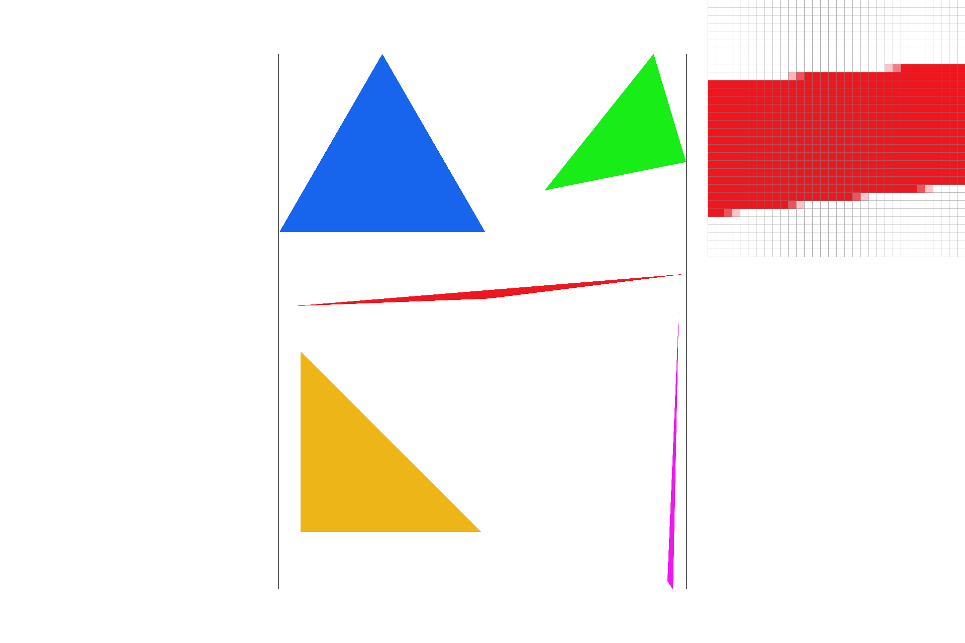
Here are screenshots of basic/test4.svg with the progression of sample rates 1, 4, and 16.
We observe blurring of the borders of the triangle as some of the subpixels on the edge are not in the triangle. This blurring creates smoother edges and as you increase the sample rate the effect becomes more dramatic as you can calculate the percentage of the pixel that is in the triangle to a higher degree of percision.

|

|

|

|
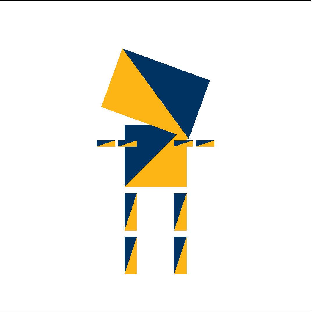
Here's my upated cubebot
#003262 and California Gold: #FDB515.
|
Barycentric coordinates are another way to specify a point. It's like taking a linear combination of each of the three points on a triangle where the weight of each point is proportional to it's proximity to the point. If you have a triangle specified by A, B, and C, you can say (x,y) = aA + bB + cC. We can interpolate the coordinates a, b, c by taking this weighted sum. As you can see in the triangle below, the weighted combination of green and blue on the right side blends the two colors. The same effect can be observed throughout the triangle; the closer you are to a point the greater weight it's color holds in the pixels color.

|

|
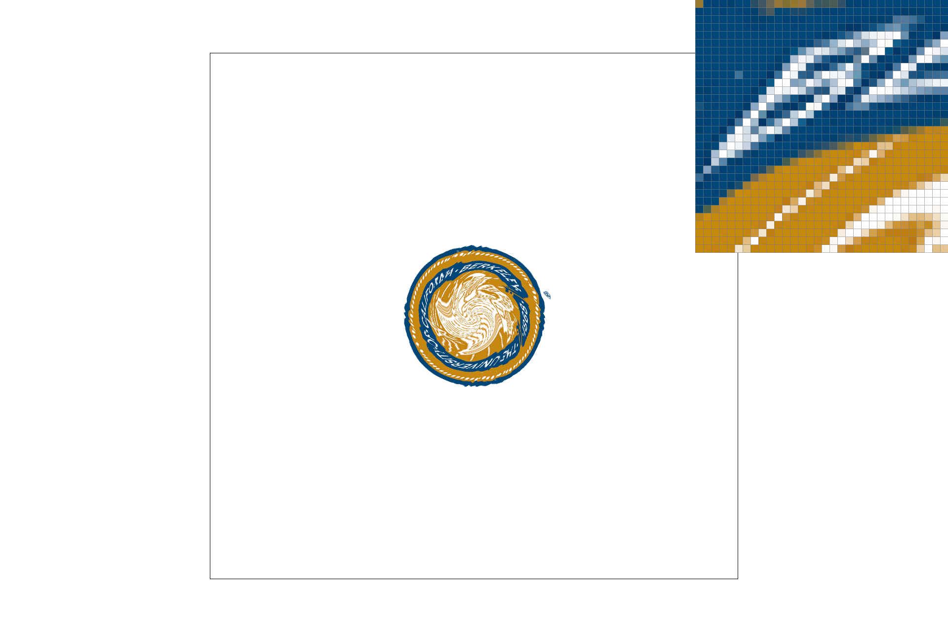
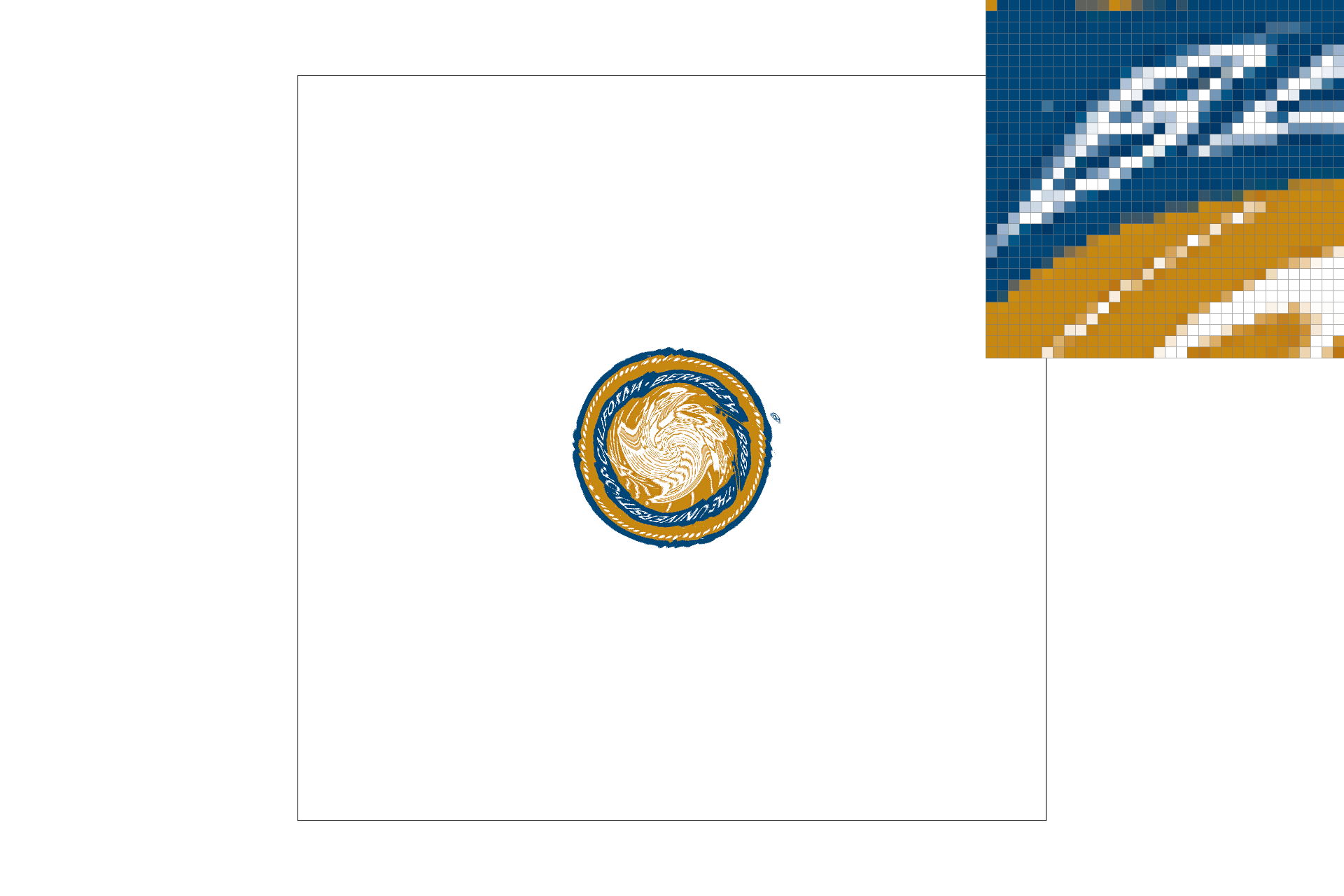
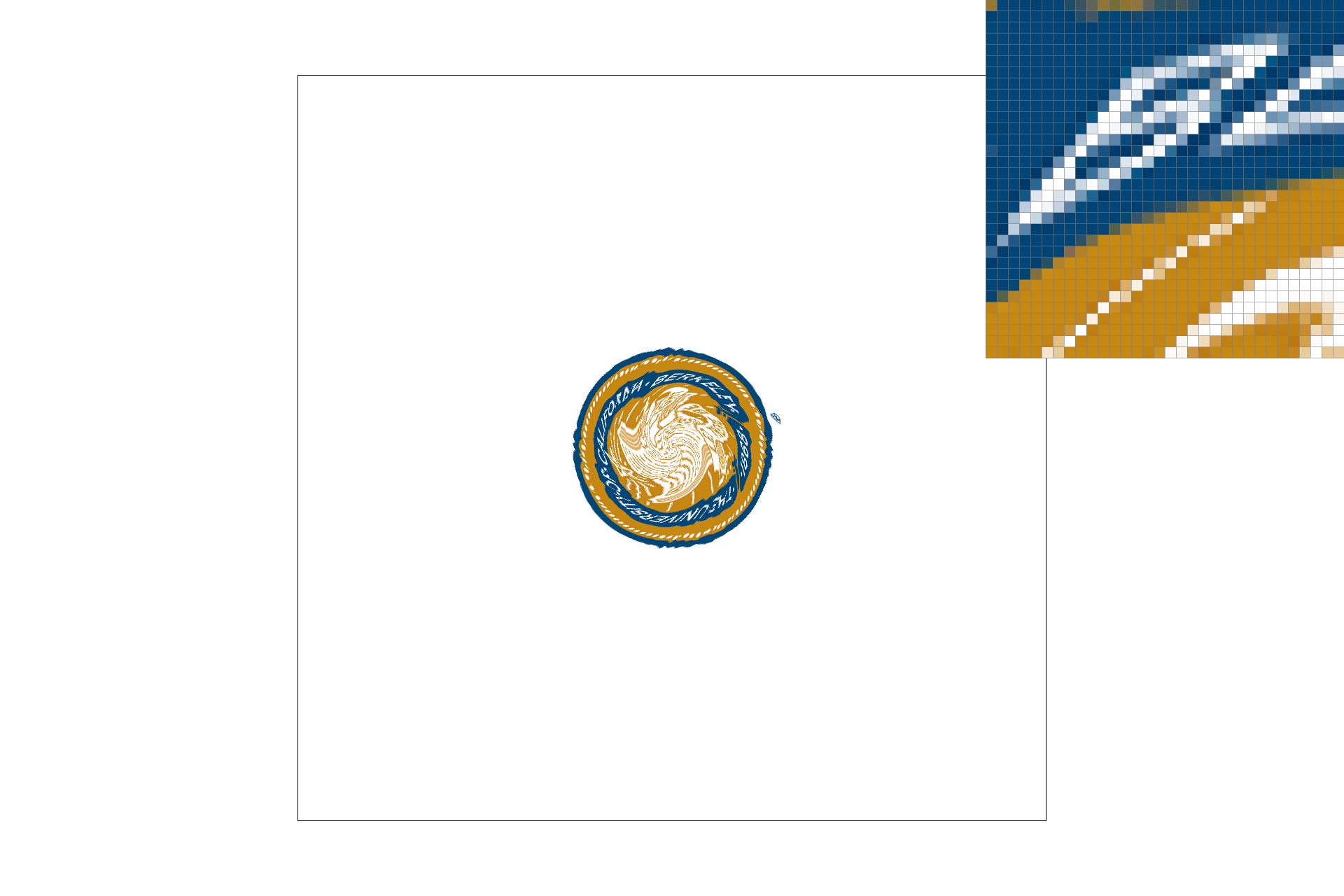
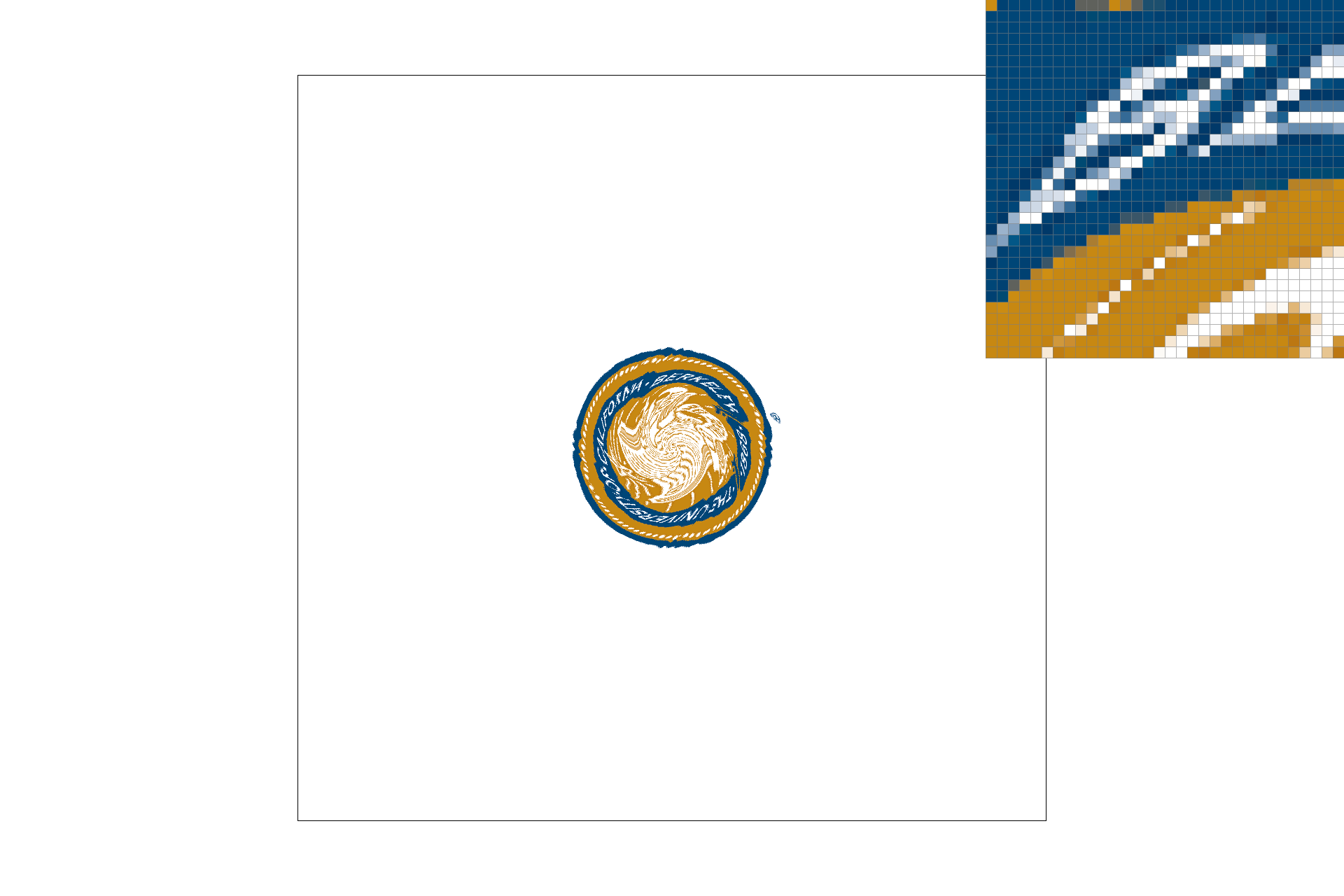
Pixel sampling works in a very similar way to rasterizing. This time, however, we are sampling a texture to color in our picture. One of the biggest challenges you have to overcome is converting coordinate spaces, which comes up when the texture picture does not map pixel-pixel with the picture you are trying to color. Given a triangle and a texture in (u, v) coordinates, you can retrieve a color for your given pixel in your picture in (x,y) coordinates by converting to barycentric coordinates just like we did in part 4. The next hurdle we have to jump is deciding which pixel to color when it doesn't map exactly. That's where Nearest Neighbor and Bilinear sampling come into play.
Here are screenshots of basic/test4.svg with the progression of sample rates 1, 4, and 16.
|
|
|
|
Bilinear removes some of the aliasing we see in the nearest samples. The sixteens also look much smoother, but that's an effect of part 2. Bilinear creates a generally more blended image as it is blending the four nearest colors it finds in the texture. There will be a large difference between the two methods when the picture is more sparse than the texture. Fine details will be ignored by nearest neighbor, but bilinear will capture some of those fine details, by blending them. Imagine 1 pixel wide lines going through the picture and they just happen to never be the nearest neighbor to the points we are sampling. These are much more likely to be incorportated into the picture with bilinear sampling, than with nearest neighbor.
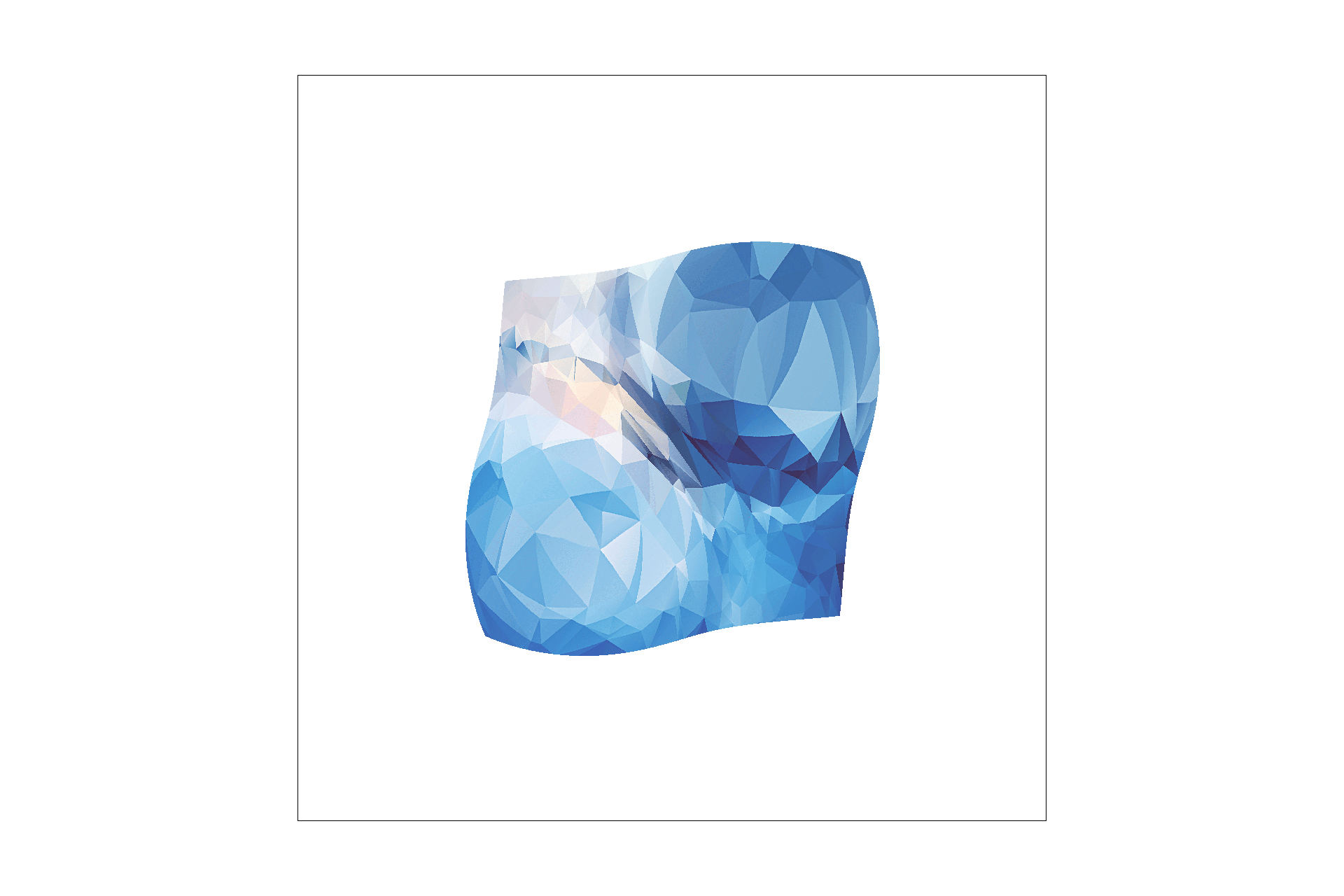
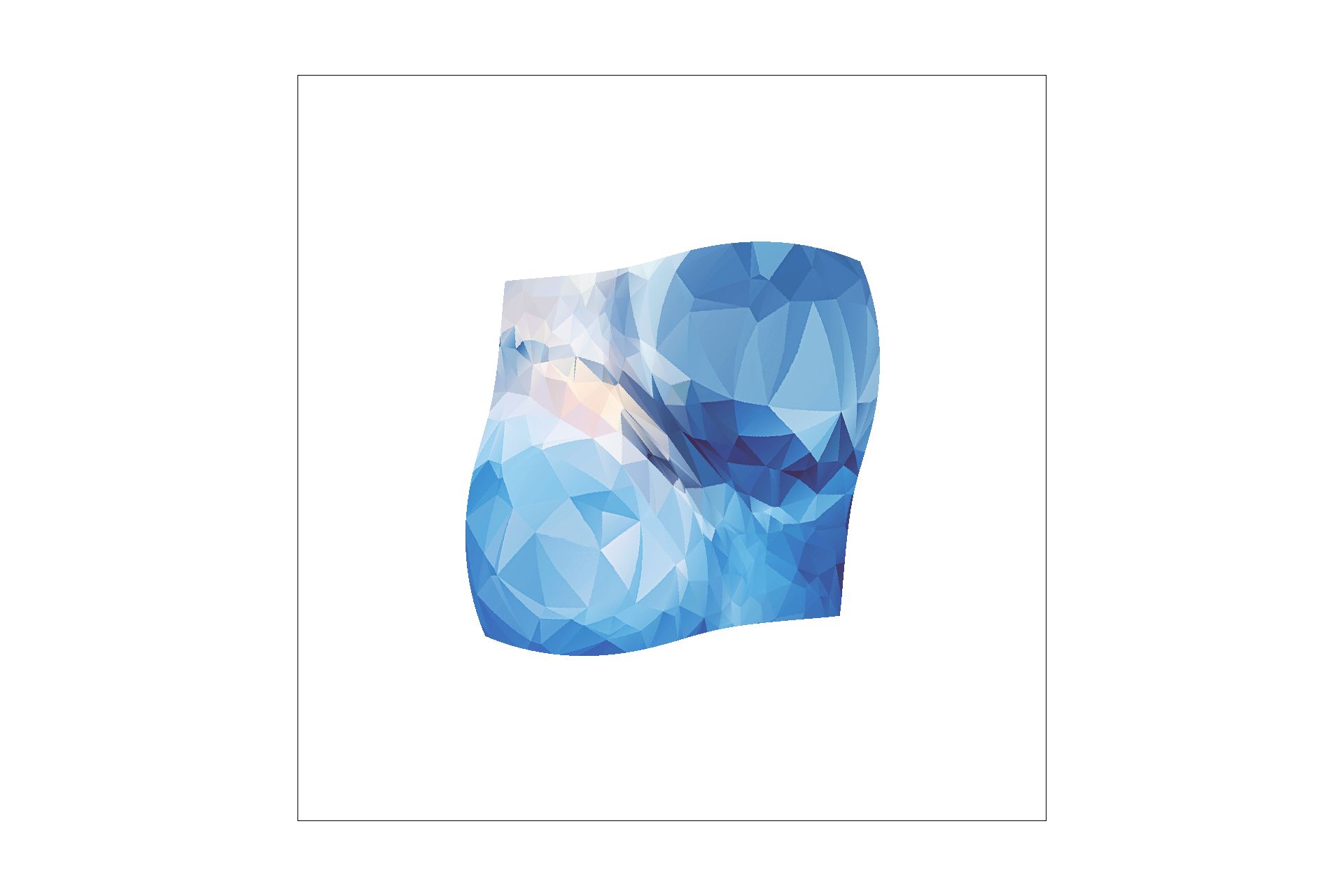
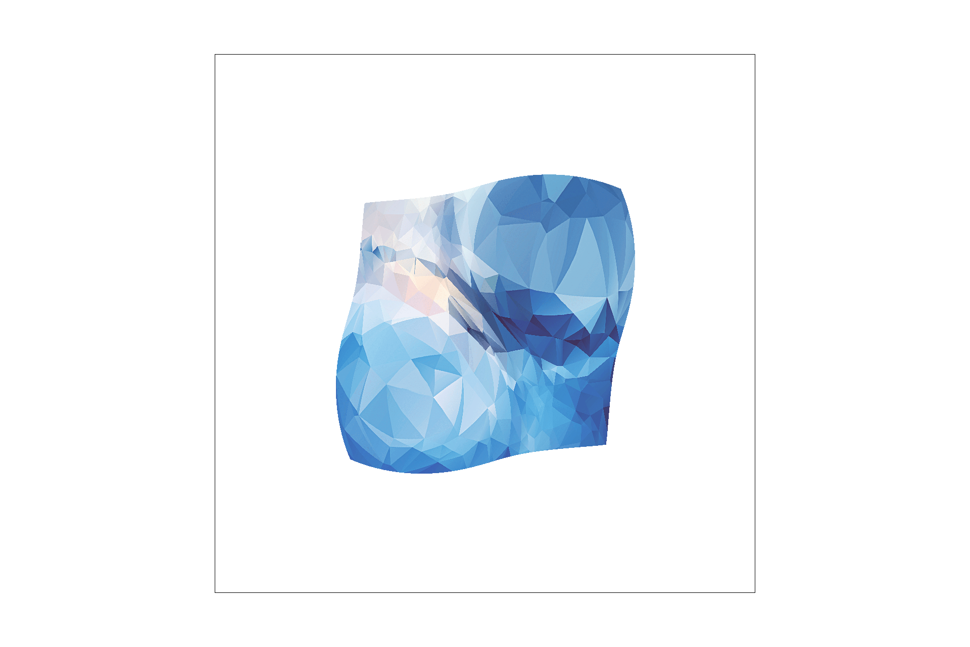
Level sampling uses the concept of a mipmap, a mapping of progressively lower resolution versions of the texture to account for the differrneces in the shapes of the texture and picture. I implemented level sampling by checking where (x+1,y) and (x, y+1) end up being in the texture plane. If they are further apart this means I should use a higher (lower resolution) mipmap level. Then that mipmap level is passed on so that I use that version of the texture rather than the full one.
The result of the getlevel computation is usually between 2 levels. In the nearest case, you just round the number and in the trilinear case, you interpolate between the two mipmap levels.
|
|
|

|
Some tradeoffs